Reading a finished brick face as if it showed the support can lead a storefront proposal to omit a structural bearing member or misidentify the surface that must carry a bond. An anchored brick veneer wall carries its weight on a foundation or another structural member, with veneer ties providing lateral support. An adhered system transfers support through the brick’s bond to its backing assembly. The visible brick pattern cannot settle that distinction.
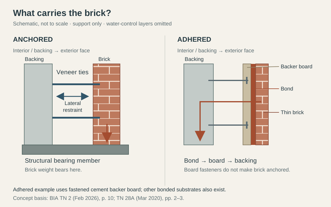
Support paths, with layers simplified. Based on BIA TN 2 (February 2026), p. 10, and TN 28A (March 2020), pp. 2–3. Arrows distinguish weight from lateral restraint; they are not a fastener layout.
Identify the unit’s attachment and vertical support
BIA’s TN 2 glossary, February 2026, p. 10, defines masonry veneer as an exterior facing that transfers out-of-plane loads to a backing without being counted as adding strength or stiffness to the wall system. Its anchored and adhered definitions explain where to look next in a section drawing.
For anchored veneer, trace the brick down to its bearing: a foundation, ledge or other structural support. Then trace the veneer ties across to the backing. These are separate jobs. A tie symbol identifies lateral restraint; it does not stand in for the member supporting the brick’s weight.
For adhered veneer, trace the bond from the brick to its substrate and then the substrate’s support. The glossary includes direct bond to masonry or concrete, and bond to a scratch coat with lath or a cement backer unit fastened to the backing. The assembly can contain screws or other fasteners while the brick units remain adhered. Hardware behind the brick is therefore insufficient evidence for calling it anchored veneer.
BIA’s TN 28A, March 2020, pp. 2–3, illustrates both support arrangements. Its main subject is adding veneer to existing houses and townhouses; it directs nonresidential applications to a design professional. The support distinction is useful here, but its residential footing and recladding details do not specify a storefront assembly.
Rule of thumb: if the drawing does not show both the vertical support and the unit’s attachment, the face photo cannot choose anchored or adhered.
Compare the mechanisms behind the face
The failure column names the mechanism to check in each assembly. It does not rank how often failures occur. Drainage bridging is discussed in TN 3C (July 2026), p. 5; bond preparation and movement are discussed in TN 28C (April 2014), pp. 9 and 7.
| System | Vertical support | Unit attachment | Dominant Failure Mode | Prevention |
|---|---|---|---|---|
| Anchored veneer | Foundation or another structural member | Veneer ties connect brick to backing for lateral support | Mortar bridges obstruct the drainage route | Preserve the specified drainage clearance and a clear route to flashing and weeps |
| Adhered veneer | Backing assembly carries the bonded facing | Bond to the designated substrate; lath or backer board may itself be fastened | Bond impaired by unsuitable surfaces; cracking from differential movement | Prepare the specified substrate and provide the appropriate movement details |
Separate the cavity from its drainage portion
BIA’s TN 3C, July 2026, pp. 4–5, discusses the 2022 edition of TMS 402/602. In that discussion, the cavity lies between the anchored veneer and its backing; the drainage space is the portion that permits water to drain. Continuous insulation can occupy part of the cavity. Calling the entire insulated cavity an empty air gap loses that distinction.
In its discussion of that edition, BIA reports a minimum drainage space of 1 in. (25.4 mm), including between brick and the exterior face of continuous insulation where present. BIA separately recommends 2 in. (51 mm) to reduce the possibility of mortar bridging. These are the source’s reported minimum and industry recommendation, respectively. They do not establish a particular storefront’s required or actual dimensions.
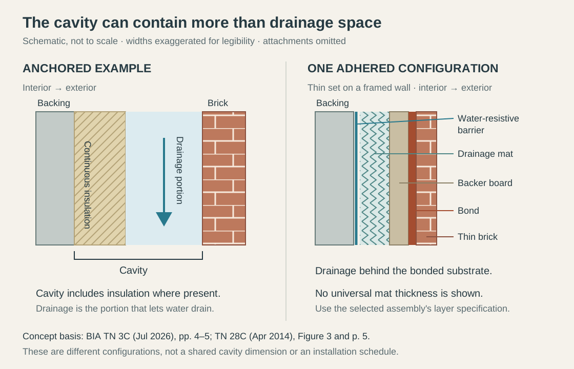
Two different configurations, not interchangeable layer schedules. Anchored terminology follows TN 3C (July 2026), pp. 4–5; the adhered arrangement follows TN 28C (April 2014), Figure 3 and its drainage discussion on pp. 3 and 5. No layer thickness is represented.
Adhered does not mean drainage-free. BIA’s TN 28C, April 2014, describes an exterior thin-set arrangement with cement backer board over a drainage mat at a stud wall. It also describes modular systems that can incorporate drainage spaces or mats. A mat behind the backer board does not change how the brick is bonded and supported. There is no universal adhered mat thickness established by these sources; the selected assembly must supply that information.
A tie schedule is a separate design question. TN 3C’s Table 2 gives prescriptive limits within the conditions discussed in that note. Choosing a schedule also needs the design method, loading, backing and tie information; a face photograph supplies none of them.
At the opening, follow the water to an outlet
An opening interrupts the wall’s layers. Read the section from the water-control layer and drainage route down to flashing, then outward to an exterior outlet. A drawing that stops at the back of a window head has left the water route unresolved.
TN 28A (March 2020), p. 2, describes water descending behind anchored veneer to flashing and weeps. For adhered construction, TN 28C (April 2014), pp. 5–6, describes flashing and weep screeds, the water-resistive barrier lapping over the flashing, and flashing at opening heads, jambs and sills. Those published principles help identify the detail to request; the outlet and interface must still belong to the selected system.
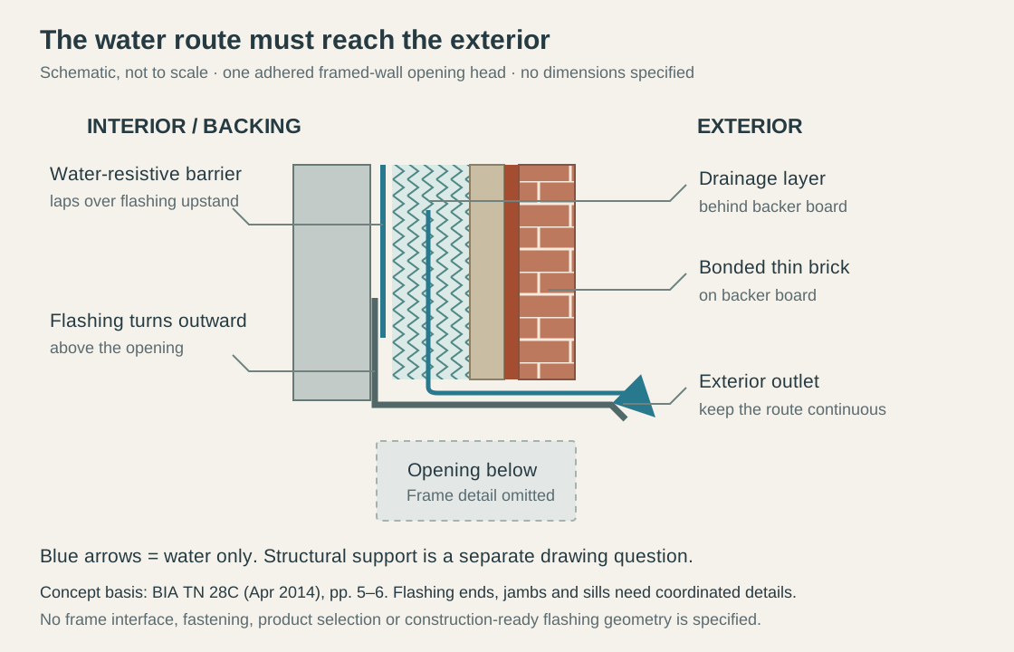
Conceptual adhered opening-head route, informed by TN 28C (April 2014), pp. 5–6. Blue arrows show water, not structural support. Jambs, sills, flashing ends and the frame interface need their own coordinated details.
Keep the brick assembly question alongside the shopfront’s other materials. The storefront materials guide covers frame, glass and gentle cleaning, while our exterior metal cladding guide compares back-ventilated titanium-zinc, PVDF aluminum, and weathering steel rainscreens across thermal expansion clips and drip kerf projections. More wall and building notes sit in the architecture section.
Keep a short drawing record
For a proposed storefront wall, record:
- The named assembly and backing material.
- The vertical support member or supported substrate.
- The brick unit’s bond or veneer ties, plus attachment of any intermediate lath, board or panel.
- The cavity contents, drainage layer and specified clearances.
- The flashing, exterior outlet and opening details that connect them.
- The applicable design documents, selected system manual and code edition.
Mark missing entries unknown. No address-specific drawings, selected manufacturer’s assembly or concealed-wall record were supplied for this article, so the actual support, dimensions and attachments remain unknown.
Method and dated sources
Prepared 19 October 2026 from BIA’s original technical notes, accessed that day: TN 2 (February 2026), p. 10; TN 3C (July 2026), pp. 2 and 4–5; TN 28A (March 2020), pp. 2–3; and TN 28C (April 2014), pp. 2–3, 5–7 and 9. These publications concern fired-clay brick. The diagrams interpret their support and drainage concepts rather than document an inspected building. TN 3C’s statements about TMS 2022 are attributed to BIA’s discussion; TN 28C’s historical code discussion does not establish current local requirements. No NYC code compliance check or project specification is claimed.