The noise reduction coefficient (NRC) is a single-number rating of sound absorption defined by the Federal Highway Administration as the arithmetic mean of the Sabine absorption coefficients at 250, 500, 1000, and 2000 Hz, rounded to the nearest multiple of 0.05, while Wikipedia places those center frequencies in four one-third-octave bands. Written in plain arithmetic, NRC equals one quarter of the sum of those four coefficients. Laboratories derive the underlying band coefficients in a reverberation room under ASTM C423 by comparing sound decay rates in the empty chamber against decay with the test specimen installed.
Because ASTM E795 ties flat-surface absorption to how a specimen is mounted, a Type A mount with no rear airspace differs in low-frequency absorption from an E-400 mount over a 400 mm airspace, and that deeper airspace may leave the printed NRC unchanged because 125 Hz sits outside the four-band mean. Operational Sabine values above 1.0 can also appear when edge diffraction makes a highly absorptive finite patch act larger than its geometric face, whereas Sound Transmission Class (STC) comes from a separate two-room partition test under ASTM E90 and ASTM E413. For broader room studies, browse our interiors archive or the full NY Sunday journal index.
What does an NRC acoustic rating mean on a finish sheet?
On an interior finish data sheet, an NRC rating summarizes the average speech-band sound absorption of one material tested in one laboratory mounting configuration. Common reporting places materials on a scale from 0.0 for very low absorption to 1.0 for very high absorption, though reverberation-room measurements can exceed 1.0 because of edge diffraction and sound fields that are not ideally diffuse. NRC is most commonly used to rate acoustic ceiling tiles, baffles, banners, office screens, and acoustic wall panels, and it is occasionally used to rate floor coverings. Intertek’s public summary of ASTM C423 notes that NRC and Sound Absorption Average (SAA) are reported for extended plane surfaces, while individual objects such as theater chairs, ceiling baffles, or space absorbers are reported in square meters per unit at one-third-octave band frequencies.
The average is rounded to the nearest 0.05 because of typical laboratory repeatability. Typical repeatability within a single laboratory is ±0.05 at 2 standard deviations, while reproducibility between different laboratories is roughly three times higher at ±0.15 for 2 standard deviations. That precision suits general-purpose rooms where speech noise build-up is the primary concern, including lobbies, reception areas, and open offices.
When readers ask how do acoustic wall panels work on a room wall, panel thickness and distance from a reflecting surface govern which frequencies a porous absorber reaches. Porous absorbers are most effective at a distance of approximately one-quarter wavelength from a reflecting surface, so increasing material thickness extends that range to lower frequencies: a 50 mm (2 in) porous absorber begins to lose effectiveness below approximately 500 Hz, while a 100 mm (4 in) sample of the same material provides useful absorption down to around 250 Hz. Under ASTM E795, test reports may identify the laboratory mounting by a type designation code rather than printing a full physical description, and if the installed backing, depth, or cavity differs from that tested mounting, the printed number does not establish the new assembly. To see how one manufacturer’s data sheet pairs mounting codes with assembly build-ups, read our guide to acoustic wall panels, NRC ratings, and mounting.
ASTM C423 also warns that laboratory absorption coefficients require judgment in real buildings because installed finish areas are usually larger than the laboratory patch and practical room sound fields are rarely diffuse.
What is the difference between NRC and STC in commercial interiors?
NRC measures sound absorbed within a room by surface finishes to dampen echoes and reverberation, whereas STC measures airborne sound transmission loss through building partitions such as walls, operable partitions, floor-ceiling assemblies, doors, windows, and roofs. Treating an absorptive wall finish as a partition barrier confuses reflection control inside one room with sound isolation between two spaces.
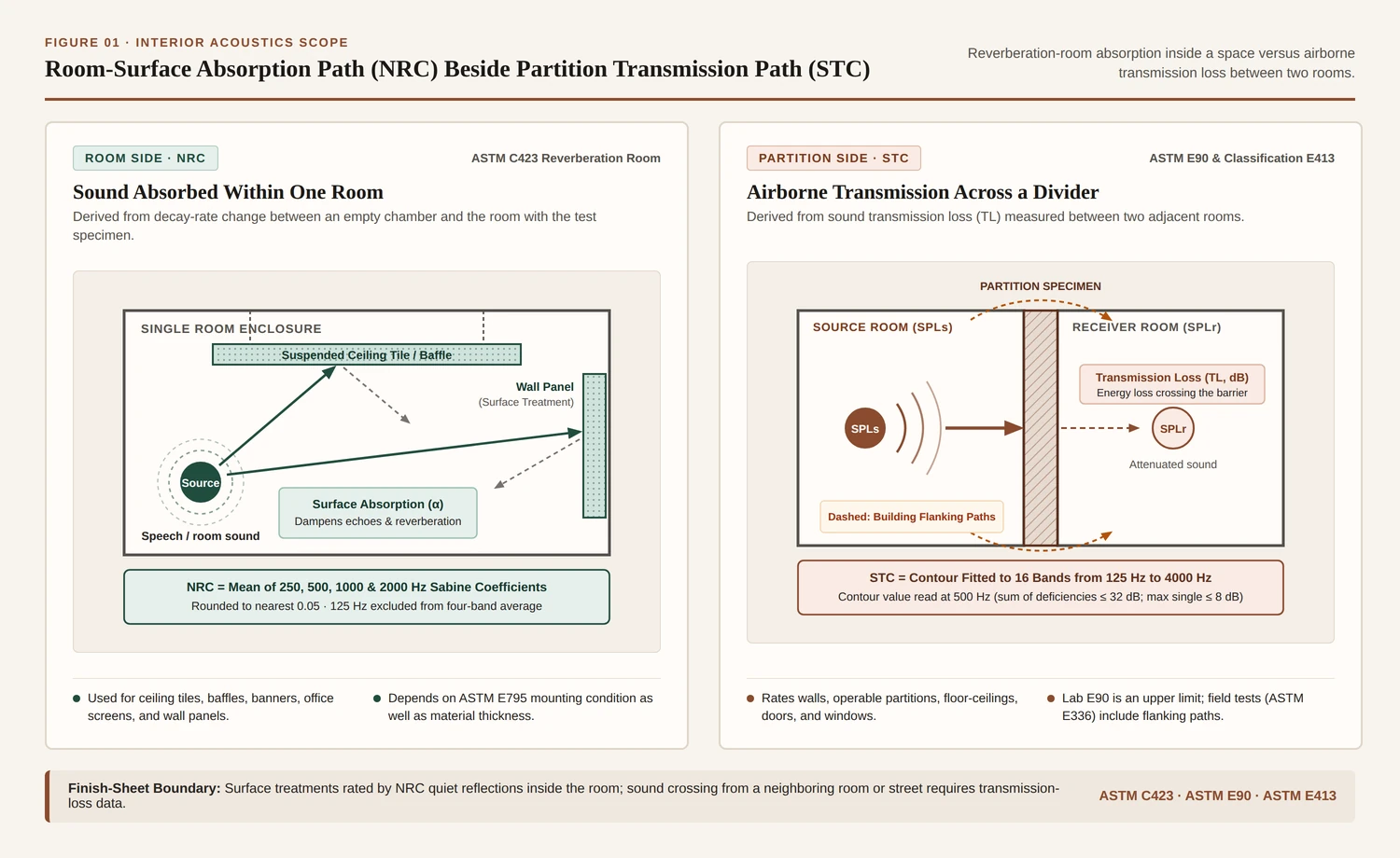
Under ASTM E90, laboratories are constructed so that the partition specimen forms the primary sound transmission path between two test rooms with approximately diffuse sound fields, and transmission loss (TL) expresses in decibels the drop between source-room sound pressure level (SPLs) and receiver-room sound pressure level (SPLr). Room absorption measured under ASTM C423 is part of the procedure for determining the sound power level of a noise source or the sound transmission loss of a partition, yet NRC and STC still answer separate questions.
| Rating dimension | Noise Reduction Coefficient (NRC) | Sound Transmission Class (STC) |
|---|---|---|
| Governing ASTM standards | Measured in a reverberation room under ASTM C423 with specimen mountings defined in ASTM E795. | Measured between two laboratory rooms under ASTM E90 and classified into a single number under ASTM E413. |
| Physical path evaluated | Sound energy absorbed at room surfaces and treatments to reduce echoes and reverberation inside the room. | Airborne sound energy lost in decibels while passing through a wall, door, window, or floor-ceiling divider. |
| Frequency bands included | Four one-third-octave center bands at 250, 500, 1000, and 2000 Hz. | Sixteen contiguous one-third-octave bands from 125 Hz to 4000 Hz inclusive. |
| Single-number rule | Arithmetic mean of the four Sabine coefficients, rounded to the nearest multiple of 0.05. | Reference contour value at 500 Hz where total deficiencies do not exceed 32 dB and no single band deficiency exceeds 8 dB. |
| Building field limitation | Installed room surfaces are larger than the lab patch and practical room sound fields are rarely diffuse. | Flanking sound transmission paths bypass the partition in real buildings, so lab STC is an upper limit compared with field tests under ASTM E336. |
In actual buildings, sound travels around a dividing wall through flanking paths, so laboratory ASTM E90 ratings represent an upper limit rather than achieved suite-to-suite isolation. Field isolation between rooms is measured instead under Test Method E336 as apparent sound transmission loss and reported through field ratings such as NIC or NNIC under ASTM E413.
ASTM E413 further restricts where STC applies: its single-number contour correlates generally with subjective impressions of speech, radio, and television noise in offices and buildings, and is not appropriate for machinery, industrial processes, bowling alleys, power transformers, musical instruments, many music systems, or transportation noise from motor vehicles, aircraft, and trains. Those sources require band-by-band frequency analysis, while a single-number rating for exterior building facade elements is given in ASTM E1332, and Intertek’s public ASTM E90 summary names that rating Outdoor-Indoor Transmission Class (OITC). In the FHWA noise barrier handbook, STC is likewise described as a rough guide for highway traffic noise spectra because for traffic noise frequencies the STC value is typically 5 to 10 dB(A) greater than the transmission loss.
How do single-band absorption coefficients differ from mounted NRC ratings?
A sound absorption coefficient states performance at one frequency band, ideally defined in ASTM C423 as the fraction of randomly incident sound power absorbed by a surface and operationally defined by reverberation decay rate. Standard ASTM C423 testing evaluates eighteen one-third-octave bands with center frequencies from 100 Hz to 5000 Hz, while NRC keeps only four of those bands and discards the rest. At the Turku University of Applied Sciences acoustics laboratory, reverberation-room testing under ISO 354 in a 9.9 m by 5.68 m by 3.57 m chamber (201 m³ volume) measures reverberation time with and without the specimen, reporting absorption coefficients from 100 to 5000 Hz in one-third-octave bands, from 125 to 4000 Hz in octave bands, and absorption classes A through E under EN 11654, while Intertek’s ASTM C423 summary states that an ISO 354 test uses a 10 m² (107.6 ft²) specimen.
Before a standard testing procedure and reverberation chamber specification existed, low-frequency absorption measurements were highly unreliable and varied widely from manufacturer to manufacturer, which is a primary historical reason NRC excluded 125 Hz (128 Hz at the time). For music rehearsal rooms, performance spaces, and rooms designed for critical speech, relying on a four-band NRC is inadequate; designers evaluate the individual one-third-octave absorption coefficients across the spectrum, including bands below 250 Hz and above 2000 Hz.
Mounting geometry makes that 125 Hz omission decisive on finish schedules. When a product sheet gives no mounting code, the test is usually Type A mounting (ABPMA mounting #4), which Wikipedia places directly on the floor, wall, or ceiling, and which the NASA Glenn and Riverbank Acoustical Laboratories paper (2015) calls A-Mount, laid directly against the chamber floor with no airspace behind the panel. Acoustical ceiling tiles, by contrast, are often tested in Type E-400 mounting, which NASA summarizes as a 400 mm airspace resembling a suspended grid ceiling (and which Wikipedia describes under Type E400 as simulating a 16-inch-deep, or 410 mm, ceiling plenum; the NASA paper notes that its test comparison of airspace depth belongs to a follow-on paper).
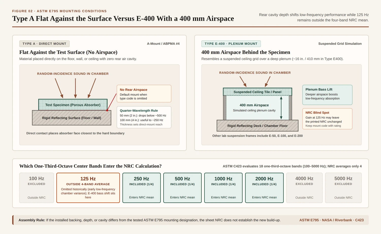
Turku’s acoustics laboratory similarly mounts panels directly on the floor (Type A) or on a Type E suspension frame in standard depths of E-50, E-100, E-200, and E-400, noting that Type E-200 places an air gap behind the plate with a total installation height of 200 mm from the floor. Adding a deeper plenum behind a ceiling tile typically raises low-frequency absorption, yet it may leave the single-number NRC unchanged because the four-band calculation does not include 125 Hz. Conversely, ASTM E795 notes that certain laboratory mountings require special fixtures or minor deviations marked “for laboratory testing only,” which should not be specified for practical installations.
How is the NRC formula averaged and why can values exceed 1.0?
The FHWA terminology guide defines NRC as the arithmetic mean of the Sabine absorption coefficients at 250, 500, 1000, and 2000 Hz, rounded to the nearest multiple of 0.05, and the FHWA acoustics section writes that mean as one quarter of the sum of those four coefficients. Wikipedia adds that while readers commonly assume NRC averages full octave-band coefficients, the ASTM C634-22 definition specifies the four one-third-octave bands at those center frequencies. In the Acoustical Society of America Standards glossary (entry 10.14), the noise reduction coefficient is defined as the arithmetic mean of sound absorption coefficients at 250, 500, 1000, and 2000 Hz, rounded to the nearest 0.05 metric sabin per square meter. Where finer speech-range resolution is needed in ASTM C423 reporting, Sound Absorption Average (SAA) averages the twelve one-third-octave band coefficients from 200 Hz to 2500 Hz and rounds to the nearest 0.01.
Specimen size and mounting angle also alter reverberation-room results. While ASTM C384 uses an impedance tube to measure normal-incidence absorption on a small sample, ASTM C423 measures random-incidence decay on a finite patch laid on the chamber floor. In the NASA and Riverbank study (2015), ASTM C423 recommends a test specimen area of 6.69 m² (72 ft²), with a minimum acceptable area of 5.57 m² (60 ft²), while Wikipedia describes it as typically 72 square feet in an 8-by-9-foot (2.4 m × 2.7 m) configuration. There is potential for greater error, or for overemphasizing acoustic efficacy, when samples are smaller than the standardized 8-by-9-foot module, and the perimeter-to-area ratio has a significant effect on the absorption.
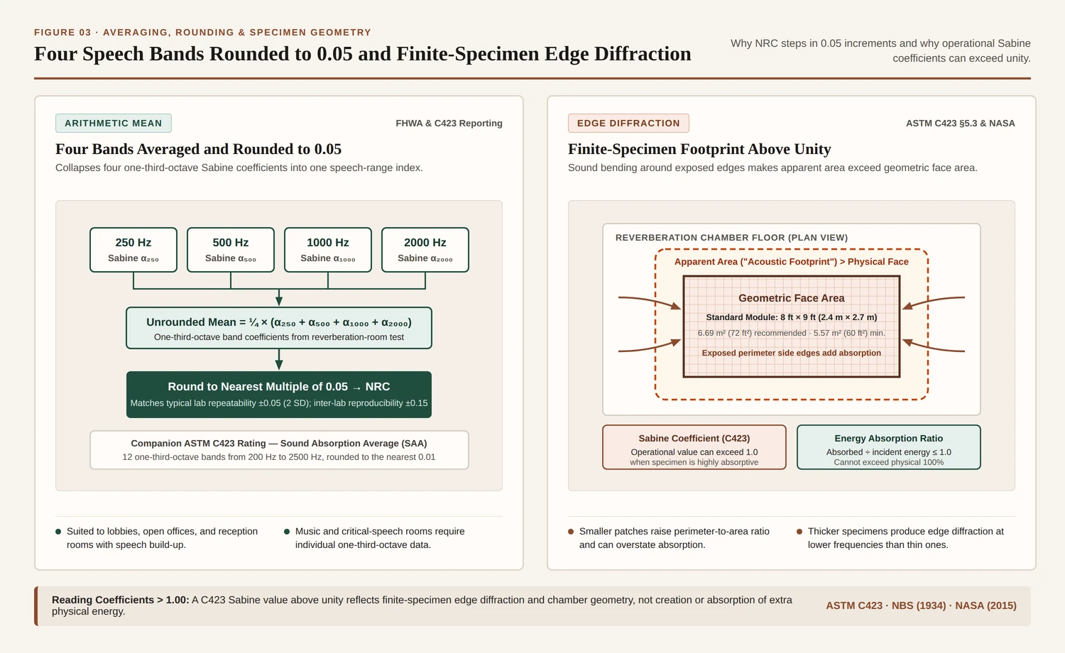
That exposed perimeter explains why legitimate laboratory reports print absorption coefficients above 1.0. ASTM C423 Section 5.3 states that diffraction effects usually make a specimen’s apparent area greater than its geometrical area, and the NASA and Riverbank study (2015) describes sound waves bending over the side edges so the acoustic footprint exceeds the geometric face; thicker specimens add side-edge area and produce edge diffraction at lower frequencies than thinner specimens. Because Sabine’s reverberant-room calculation divides total measured absorption by the geometric face area alone, highly absorptive specimens can yield operational Sabine absorption coefficients greater than 1.0. NASA distinguishes that operational Sabine value from the physical acoustic Energy Absorption Coefficient, defined as absorbed energy divided by incident energy, which cannot exceed 1.0.
Early reverberation-room studies documented both the edge effect and the limits of the decay equation. In a National Bureau of Standards research paper (1934), Chrisler observed that coefficients computed from 72 sq ft specimens in some cases exceeded 100 percent even when the specimen edges were covered with angle iron, concluding that diffraction or a similar phenomenon rather than edge absorption caused the increase. In an earlier National Bureau of Standards paper (1930), the authors noted that if reverberation time becomes very small in a room with much absorbing material, the absorption value computed from the decay equation often exceeds unity, which is an absurd consequence of that equation and not a modern rule for discarding ASTM C423 test sheets.
How do hard surfaces and acoustic finishes compare on an NRC chart?
When comparing finishes across a specification schedule, read the mounting code and the band table rather than treating NRC as a fixed 0.0 to 1.0 material constant. In the FHWA highway noise barrier design handbook, barrier NRC values are described on a scale from zero (reflecting incident sound) to one (absorbing incident sound), with typical absorptive highway barriers ranging from 0.6 to 0.9. Inside architectural reverberation-room testing under ASTM C423, however, operational coefficients on highly absorptive panels can still exceed unity through finite-specimen diffraction, and two products with identical rounded NRC figures can differ across the uncounted bands from 100 Hz to 5000 Hz, especially at 125 Hz.
For hospitality dining rooms considering cafe acoustic panels alongside existing plaster, timber tables, and upholstered seating, separate the sensory room survey from laboratory sheet verification. Our companion essay on cafe acoustics and surfaces examines how parallel hard planes and soft furnishings shape everyday conversation in neighborhood rooms before product testing enters the scope.
Finish-sheet acoustic checklist for dining rooms and retail interiors
Before approving an interior finish schedule or substituting an adhesively applied panel for a suspended assembly, check six items on the laboratory report:
- Verify that the ASTM E795 mounting designation on the test report, such as Type A direct contact or Type E-400 over a 400 mm airspace, matches the actual backing and cavity depth on the architectural detail.
- Review the four individual one-third-octave Sabine absorption coefficients at 250, 500, 1000, and 2000 Hz beside the rounded 0.05 NRC average or twelve-band 0.01 SAA figure.
- Check whether the 125 Hz band and bands above 2000 Hz are reported on the ASTM C423 table whenever low-frequency mechanical rumble, music playback, or critical speech applies to the room.
- Confirm the tested specimen area against the recommended 6.69 m² (72 ft²) and the 5.57 m² (60 ft²) minimum, and against the standardized 8-by-9-foot module, so a smaller sample does not overstate absorption through the perimeter-to-area ratio.
- Note the specimen thickness and perimeter edge framing condition recorded during the ASTM C423 test when reading Sabine coefficients near or above unity.
- Require a separate partition transmission-loss test under ASTM E90 and ASTM E413 (or field apparent transmission loss under ASTM E336, or facade classification under ASTM E1332) whenever the acoustic problem involves an adjacent tenant space, mechanical room, or street front.